


CD Systems Manufacturing
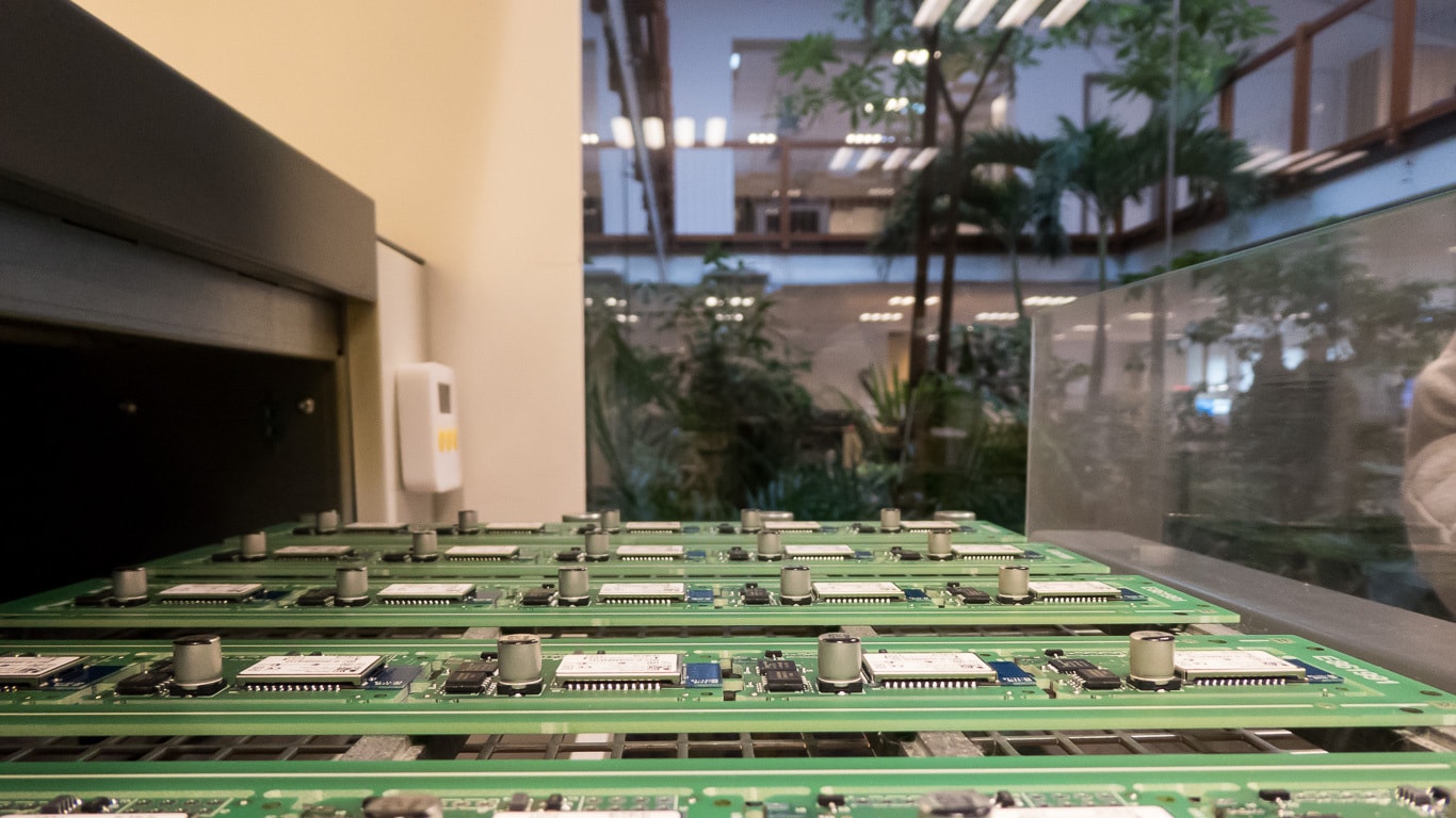
CD Systems Manufacturing produces and packages all high-quality electronics.
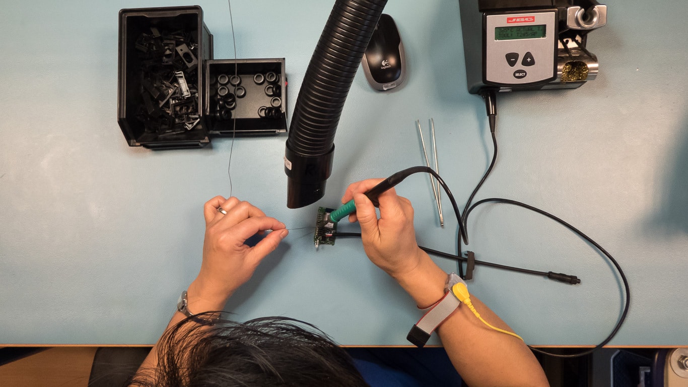
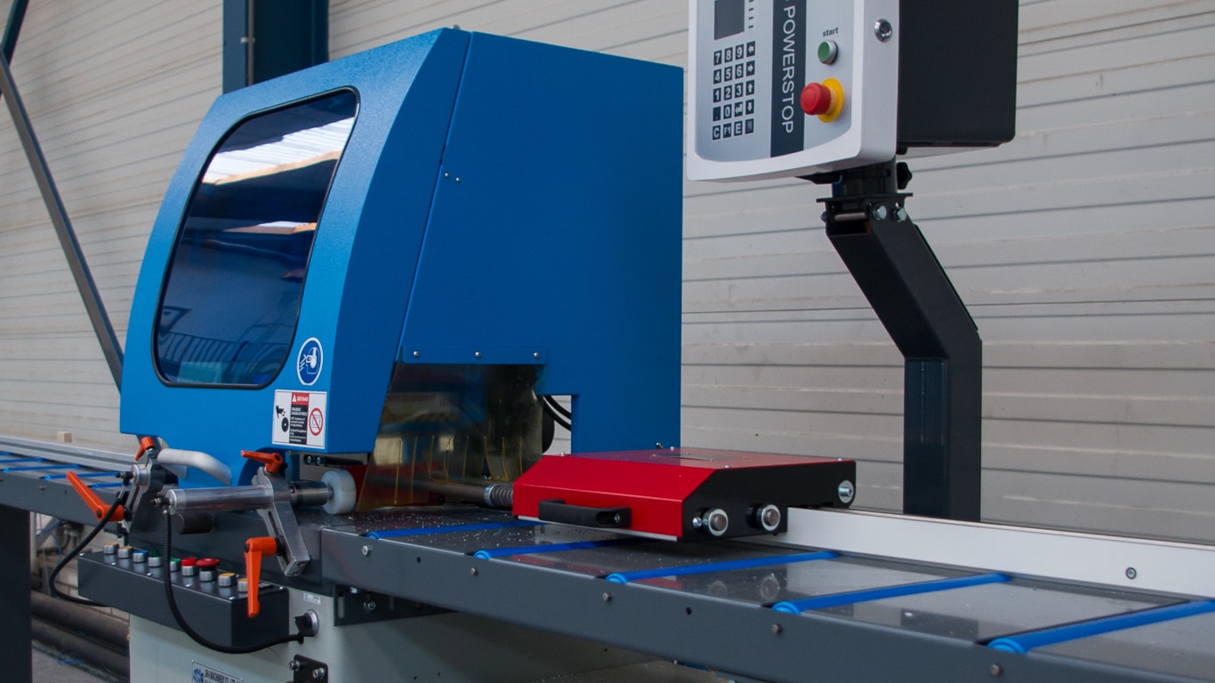
Equipped with a high-tech machine park including a pick & place machine, laser cutting and 3D printing, CD Systems is able to produce and assemble all kinds of electronics. From prototyping to mass production. All products are tested punctually and are ready to use.
Solder stations are equipped with air extraction and anti-static bracelets. The production room has an anti-static flooring system. Temperature, humidity and CO2 are regulated to ensure a healthy work environment.


